
Modbus TCP (`TCP :502`) & Modbus RTU (`RS-485`) Connectors: How They Work & Setup Guide
Document ID: REF-CONNECTOR-MODBUS-GXPHISTORIAN-2026
Protocols Covered: Modbus TCP/IP over TCP Port 502 and Modbus RTU (Remote Terminal Unit) over EIA-485 (2-Wire / 4-Wire) and EIA-232 bridged via Modbus TCP Gateways (Moxa MGate MB3180)
Typical Biopharma Equipment: PMS LasAir® III / Pro & Airnet® II Particle Counters, Veolia Sievers® M9 / 500 RL WFI TOC Analyzers, Hamilton Arc® Smart Probes (Incyte VCD, VisiFerm DO, EasyFerm pH), BINDER KBF Stability Chambers, Thermo CryoMed™ Freezers, Brooks SLA Mass Flow Controllers, and Advantech ADAM-6015 / 6017 Remote I/O Modules
1. Visual Architecture: How Modbus TCP & Modbus RTU Work Under the Hood
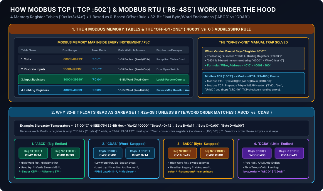
Originally developed by Modicon in 1979, Modbus remains the universal lingua franca of smart sensors, particle counters, TOC analyzers, and environmental chambers because of its simplicity. However, 90% of Modbus commissioning issues come down to two things:
- The “Off-by-One” Register Addressing Rule (
40101vs. Wire Offset100). - 32-Bit IEEE-754 Float Byte/Word Endianness (
ABCDBig-Endian vs.CDABWord-Swapped).
The visual diagram below explains both concepts at a glance:
2. Physical Appearance & Wiring: Modbus TCP vs. Modbus RTU
2.1 Modbus TCP (TCP Port 502)
- What It Looks Like: Standard RJ45 Ethernet port on the back or bottom of the analyzer (e.g., Veolia Sievers® M9, Binder KBF Stability Chamber, PMS Airnet® II / LasAir® III, Advantech ADAM-6017).
- How It Connects: Plug a Cat6/Cat6A cable directly into your GMP instrument switch.
GxPHistorian’s Telegraf[[inputs.modbus]]plugin pollstcp://<IP_ADDRESS>:502directly.
2.2 Modbus RTU (RS-485 2-Wire Screw Terminal or M12 8-Pin)
Many field sensors—such as Hamilton Arc® pH/DO/Permittivity probes mounted directly in bioreactor ports, older cleanroom particle counters, or chiller controllers—use 2-wire RS-485 Modbus RTU.
- What It Looks Like:
- Either a 3-pin green screw terminal (
Data+ / B,Data- / A,GND) or an 8-pin M12 A-coded circular plug (Hamilton Ref 242079cable).
- Either a 3-pin green screw terminal (
- The 4 Rules of Bulletproof RS-485 Modbus RTU Wiring:
- Daisy-Chain Topology Only: Wire
D+toD+,D-toD-, andGNDtoGNDfrom instrument 1 instrument 2 … Moxa MGate MB3180 gateway (up to 32 devices per segment, up to total cable length). - End-of-Line Termination Resistors: Place a quarter-watt resistor across
D+andD-at the very first device and enable the built-in termination switch on the Moxa MGate MB3180 at the other end. This absorbs signal reflections at the ends of the transmission line. - Unique Slave ID (
1..247) & Identical Serial Framing: Every device on the same RS-485 wire must share the exact same baud rate and parity (e.g.,19200, 8, N, 2for Hamilton Arc or9600, 8, E, 1for industrial meters), and each device must have a unique Unit / Slave ID (1,2,3, …). - Vendor Polarity Naming Quirk (
A/BvsD+/D-): Most vendors labelD+ = BandD- = A, but a few vendors reverseAandB. Practical tip: ConnectingD+andD-backwards will never damage an RS-485 chip—if a new device doesn’t reply, simply swap the twoD+/D-wires!
- Daisy-Chain Topology Only: Wire
3. How the 4 Modbus Memory Tables & Function Codes Work
Inside every Modbus device, memory is divided into four separate tables distinguished by the Function Code (FC) sent in the request packet:
| Table Number | Table Name | Traditional 5-Digit Doc Address | Modern 6-Digit Doc Address | Modbus Function Code (Read) | Data Width | Access | Typical Biopharma Usage |
|---|---|---|---|---|---|---|---|
0xxxx | Coils | 00001 – 09999 | 000001 – 065536 | FC 01 (Read Coils) | 1-Bit (0 or 1) | Read / Write | Discrete command relays (e.g., Start/Stop sample pump). |
1xxxx | Discrete Inputs | 10001 – 19999 | 100001 – 165536 | FC 02 (Read Discrete Inputs) | 1-Bit (0 or 1) | Read-Only | Hardware limit switches (Door_Open, Flow_Switch_OK, High_Temp_Alarm). |
3xxxx | Input Registers | 30001 – 39999 | 300001 – 365536 | FC 04 (Read Input Registers) | 16-Bit Word (2 Bytes) | Read-Only | Read-only live sensor measurements (PMS LasAir® III particle counts, Advantech ADAM RTD temperatures). |
4xxxx | Holding Registers | 40001 – 49999 | 400001 – 465536 | FC 03 (Read Holding Registers) | 16-Bit Word (2 Bytes) | Read / Write | Universal process registers (Veolia Sievers® M9 TOC/Cond, Hamilton Arc® probes, Binder KBF temp/humidity). |
Solving the “Off-by-One” (40001 vs 0) Addressing Trap
- In old Modicon PLC manuals, register numbers started at
1(30001= first Input Register,40001= first Holding Register). - However, on the actual Ethernet/serial wire, register addresses start at
0(0x0000)! - Rule:
- If a vendor manual lists “Holding Register
40101”, strip the leading4(which just tells you to useholding_registers/FC 03) and subtract1: - If a modern vendor manual (like Hamilton Arc® or Binder KBF) already lists 0-based addresses (e.g., “Register Address
2088(0x0828), Function Code03”), use2088directly ([2088, 2089])!
- If a vendor manual lists “Holding Register
4. How 32-Bit IEEE-754 Float Byte/Word Ordering (ABCD vs CDAB) Works
Because a standard Modbus register is only 16 bits (2 bytes) wide, any 32-bit Floating Point (FLOAT32-IEEE) or 32-bit Integer (INT32 / UINT32) measurement requires reading two consecutive 16-bit registers ([N, N+1])—a total of 4 bytes (A, B, C, D).
Take a bioreactor temperature of 37.00 °C, which in IEEE-754 32-bit floating-point hexadecimal is 0x42140000 (Byte A = 0x42, Byte B = 0x14, Byte C = 0x00, Byte D = 0x00):
Telegraf byte_order Setting | Register N (First 16-Bit Word) | Register N+1 (Second 16-Bit Word) | Common Name | Biopharma Instruments Using This Order |
|---|---|---|---|---|
"ABCD" | 0x4214 (A B) | 0x0000 (C D) | Big-Endian (High Word First) | Veolia Sievers® M9 TOC, Binder KBF Stability Chambers, Siemens S7, Advantech ADAM |
"CDAB" | 0x0000 (C D) | 0x4214 (A B) | Word-Swapped (Low Word First) | Hamilton Arc® Smart Probes (Incyte, VisiFerm, EasyFerm), PMS LasAir® III, Schneider Modicon |
"BADC" | 0x1442 (B A) | 0x0000 (D C) | Byte-Swapped Big-Endian | Legacy Yokogawa recorders, select Rosemount HART gateways |
"DCBA" | 0x0000 (D C) | 0x1442 (B A) | True Little-Endian | Select embedded ARM/x86 custom skids |
Instant Diagnostic Tip: If your Modbus temperature tag in
GxPHistorianreads a bizarre scientific notation number like1.42e-38or-2.84e+29, your physical wiring and register address are working—simply changebyte_order = "ABCD"tobyte_order = "CDAB"intelegraf.conf!
5. How Modbus Exception Codes & Quality Mapping Work
When a Modbus request succeeds, GxPHistorian records quality = 192 (Good). If the instrument returns a Modbus Exception Frame (where the Function Code has its highest bit set, e.g., 0x83 or 0x84) or a TCP/CRC timeout occurs, GxPHistorian flags the issue immediately:
| Modbus Exception Code | Name | Meaning & Cause |
|---|---|---|
0x01 | ILLEGAL FUNCTION | You queried holding_registers (FC 03), but the vendor stored the data in input_registers (FC 04). |
0x02 | ILLEGAL DATA ADDRESS | Register offset is off by 1 (40101 vs 100), or you requested only 1 register ([2088]) of a 2-register 32-bit float ([2088, 2089]). |
0x03 | ILLEGAL DATA VALUE | Requested block size exceeds the device’s max register count per packet (max 125 registers per FC 03/04 call). |
0x04 | SLAVE DEVICE FAILURE | Unrecoverable hardware/sensor fault inside the instrument maps to quality = 0 (Bad). |
0x0A / 0x0B | GATEWAY PATH / TARGET FAILED TO RESPOND | The Moxa MGate MB3180 Ethernet side is reachable on Port 502, but the downstream RS-485 instrument (Slave ID) is powered off or unplugged! |
6. Production Telegraf Configuration (edge-collector/telegraf-clickhouse.conf)
# Example 1: Veolia Sievers M9 WFI TOC Analyzer (Big-Endian ABCD Float32 over Modbus TCP)[[inputs.modbus]]  name = "sensor_data"  controller = "tcp://10.20.90.30:502"  slave_id = 1  timeout = "3s"  interval = "10s"  configuration_type = "register"
  holding_registers = [    { name = "val", byte_order = "ABCD", data_type = "FLOAT32-IEEE", scale = 1.0, address = [100, 101] }  ]  [inputs.modbus.tags]    tag_id = "501" # WFI_LOOP01_TOC_PPB
# Example 2: Hamilton VisiFerm Optical DO Probe via Moxa MGate MB3180 (Word-Swapped CDAB Float32)[[inputs.modbus]]  name = "sensor_data"  controller = "tcp://10.20.50.40:502"  slave_id = 2  timeout = "2s"  interval = "1s"  configuration_type = "register"
  holding_registers = [    { name = "val", byte_order = "CDAB", data_type = "FLOAT32-IEEE", scale = 1.0, address = [2088, 2089] }  ]  [inputs.modbus.tags]    tag_id = "104" # BR201_DO_PV